Disclaimer
This project was hacked together against a deadline for Teletext Block Party 2018. The design has flaws, and the construction leaves a lot to be desired. This article merely describes what I built and why. I gave the project a ridiculous name on purpose.
Project Goals
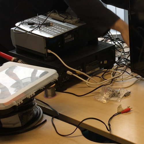 Photo courtesy of PJ Fagan
The genesis of this project was the Teletext Block Party at the Centre For Computing History in February 2017. For that event I bodged together a four channel UHF distribution system from two VCRs, the guts of a Sony camcorder modulator, and a borrowed standalone UHF modulator unit.
These were fed composite video from assorted Raspberry Pi computers running raspi-teletext and the UHF signals combined with a huge spaghetti-like mess of low quality patch cables resulting in a great deal of signal reflections and futile fault finding.
I decided on that weekend that I should build a plug and play system if we ever held the event again.
The basic design requirements then were four Raspberry Pi boards sending composite video to four UHF modulators, the signals combined and amplified for distribution to multiple TVs.
Components
A friend gave me two unwanted Raspberry Pi zero boards which made sense to use for an embedded application like this. In my infinite wisdom I decided to do the opposite of everybody else and fit 0.1″ female headers to the zeros and male headers to the motherboard.
I had originally expected to use simple manually tuned UHF modulators but couldn’t find any for sale with a wide frequency range or in quantities greater than one. Then by widening my search I came across a German ebay shop selling new-old-stock programmable UHF modulators (ALPS MDLP3W104A). I immediately ordered five units (four for the project plus one for blowing-up allowance) since the postage far outweighed the cost of each device. I’m glad I did because a few weeks later I shared the link with someone online who reported back that the company now refuse to ship to the UK.
The modulators are programmed using an I²C interface, and must be initialised every time they are powered up. I briefly considered using an ATTiny to bit-bang all four modulators, before realising that it made much more sense to have each Raspberry Pi program its own modulator.
A pair of BSS138 n-channel mosfets are used as an I²C level shifter to interface the 5V modulator with the 3.3V I/O of the Raspberry Pi. This wasn’t strictly necessary as the Pi was able to communicate without, however the high level was right on the edge of being valid for the modulator’s input threshold.
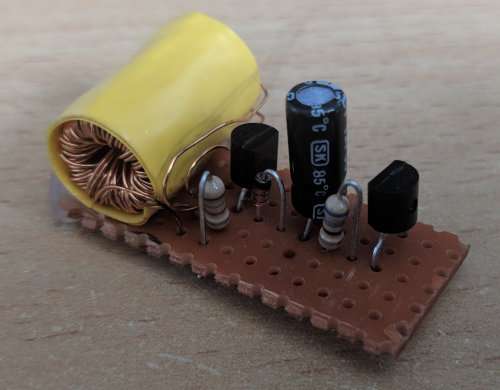
The modulators require a low current 30 ±3 volt tuning supply. To achieve this I built a "joule thief" circuit with a KA33VTA voltage stabilizer.
The four channels were split across two boards, both constructed on 0.1″ square pad prototyping board.
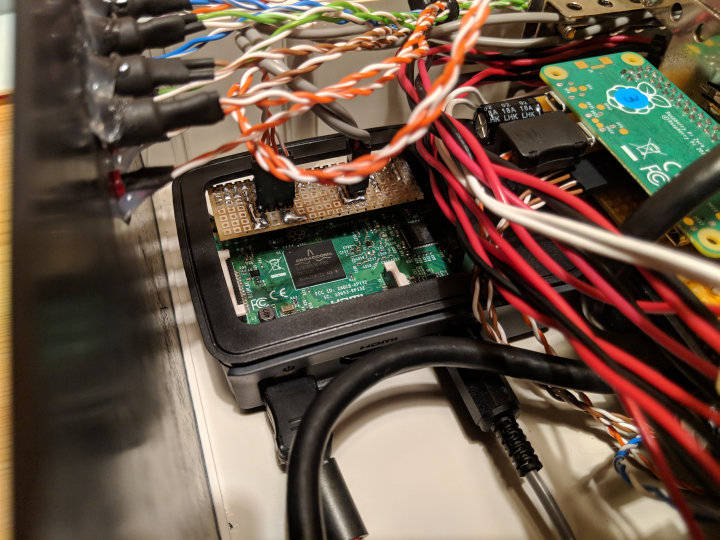
As the Raspberry Pi zero has no network hardware (unlike the zero W wireless model) I added a Raspberry Pi model 3B to host four USB CDC network links with the Pi zeros. The Pi 3B routes traffic from the zeros over the WIFI network, and forwards four ports to the zeros to allow direct ssh/sftp connections for configuration and port 80 for the Block Party editing server.
The Pi zeros are powered through the GPIO headers from the main boards.
Feature Creep
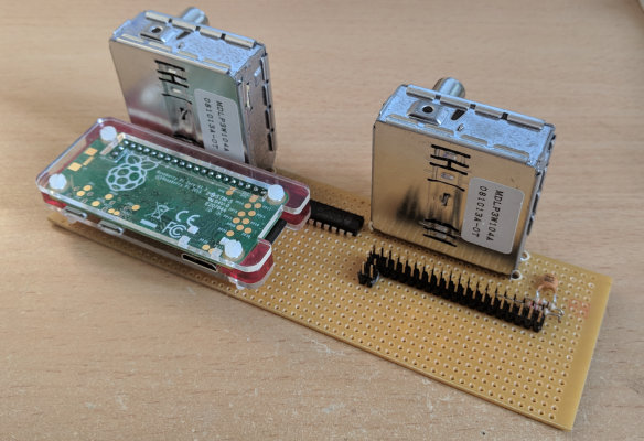
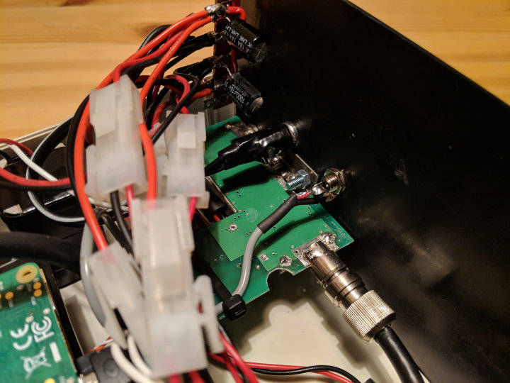
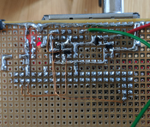 Photo an early version of the circuit
With the basic functionality worked out I began thinking of what else would be "nice to have". Since the modulators power up in an unprogrammed state they would be generating spurious signals until the Raspberry Pi zeros completed their boot sequence, or constantly if a Pi was unplugged etc. I therefore decided to add a high side switch using a DMG2307L p-channel mosfet to power each modulator. The 5V side of the I²C level shifter is also powered from this switched supply, along with an indicator LED. The modulators are therefore unpowered by default and only operate when a GPIO pin is driven high on the Raspberry Pi.
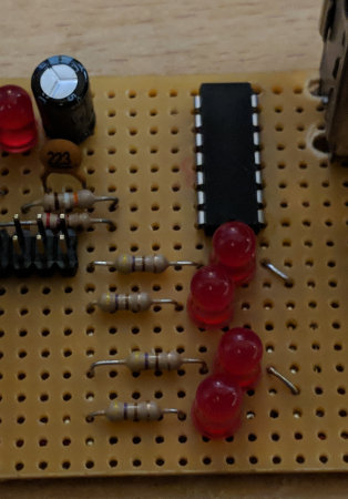 Audio switching and blinkenlights
As the Raspberry Pi zero has no audio output, I constructed a single channel copy of the original Raspberry Pi audio filter connected to GPIO 18 with an overlay in the boot config to configure it as PWM0. Rather than connect this directly to the modulator’s audio input I decided to add a pair of 4066 quad bilateral switches to allow each modulator’s audio input to be switched between the Pi zero and a common auxiliary input under software control. Some simple logic to drive the switch inputs from a 3.3V GPIO output was again built from BSS138 mosfets and included superfluous LED indicators to show the selected audio source. By default the auxiliary audio input is selected until a Pi zero raises the relevant GPIO output.
The Pi model 3B has a stereo audio output, however this includes DC blocking capacitors. Rather than build DC biasing to shift the signal above the 0V rail to allow it to pass through the 4066 switches, I simply repeated the circuit I had used for the Pi zeros.
As each Pi must be shut down before the power can be safely removed, and the zeros would be inaccessible over the network in the event that the USB links failed to connect, I decided to wire up a boot/shutdown button and activity LED to each Pi. On the Pi 3B the button is connected to GPIO 3 and configured in the boot config to shutdown when that pin is pulled low (GPIO 3 is hard coded to boot the Pi from the Halt state when pulled low). Since the Pi zeros are using GPIO 3 to communicate with the modulators (GPIO 3 is the I²C SCL pin) an alternative GPIO pin was configured as the shutdown button, two 1N4148 signal diodes allow the button to pull both pins down.
A panel mount phono socket allows external access to the Pi 3B’s composite video output, so that it is possible to log in using a bluetooth keyboard and configure the wireless network without opening the project case.
Construction
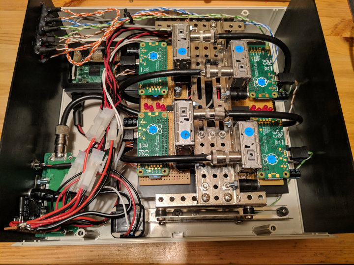 The project was mounted in a 291 x 264 x 111mm ABS project box. The two main circuit boards were mounted by the modulator bodies to a framework made from East German metal construction kit parts. This frame is screwed to mounting points inside the project box by small self tapping screws and also holds the four port antenna splitter which is used here in reverse as a signal combiner. A short coax patch cable connects the output of each modulator to the combiner, then from the combiner to the input of an antenna booster board salvaged from a mains powered unit and mounted to the end panel of the project box. The output of the booster amplifier protrudes through a hole in the project box and becomes the output of the whole project, to be fed into an 8-port antenna splitter feeding the televisions at the Block Party event.
The Raspberry Pi 3B is mounted in the official case, and stuck to the bottom of the project box using two strips of adhesive backed velcro.
Software
The teletext signals were again generated using raspi-teletext, though I created my own fork to add the ability to use particular VBI lines rather than transmit the full 16 lines per field. [The line masking feature has now been merged into the official version - August 2019]
This allowed a more genuine playback of captured broadcast teletext, and was necessary to permit a demonstration of the TTX2000S teletext decoder for the Sinclair ZX Spectrum.
At the 2017 event each Pi showed a simple test card on the video signal, but for 2018 I was eager to go one better and have a full video capability. As before, each Pi generated a test card using pngview, but this time I wrote a simple bash script to loop through a directory of video files playing each in turn with omxplayer. A short sleep between each video allowed the test card to be seen, identifying the channel.
One of the channels showed a playlist of teletext related documentary and promotional films, while another ran a playlist of teletext speed-art videos by Steve “Horsenburger” Horsley. The remaining two channels just showed their test cards.
A script on the Pi 3B looped through directories of over 20 hours of “Pages from Ceefax” music compilations, using the SoX play command to play an m3u playlist in each directory. The script keeps track of which directory it is playing in a file and resumes the looping from there when next run so there were no repeats across the two days.
The zero displaying the documentary films switched the modulator to its own audio output, while the other three modulators played the “Pages from Ceefax” music from the auxiliary input. This meant the background music at the Block Party remained synchronised when tuning the televisions to different channels.
Control of the hardware was achieved using python scripts, which were run as required on boot by a bash script invoked from a boot time cron job.
The startup script on the zeros first sleeps for 10 seconds to allow the boot process to complete, before modifying the video synchronisation registers using the raspi-teletext tvctl program to allow drawing in the VBI. It then starts either vbit2 or a teletext capture playback script.
Next a script is started to display a test card using pngview, before calling a python script to power up the modulator.
Another python script programs the desired UHF channel number, and a third switches the audio feed if required. Finally on two of the zeros it launches the video playback shell script.
As with Block Party 2017 there were two channels playing back old broadcast teletext (in this case an example of Ceefax from 2006 and Channel 4 Teletext from 2007), a channel outputting the community run Teefax service, and finally a channel running a service just for the event.
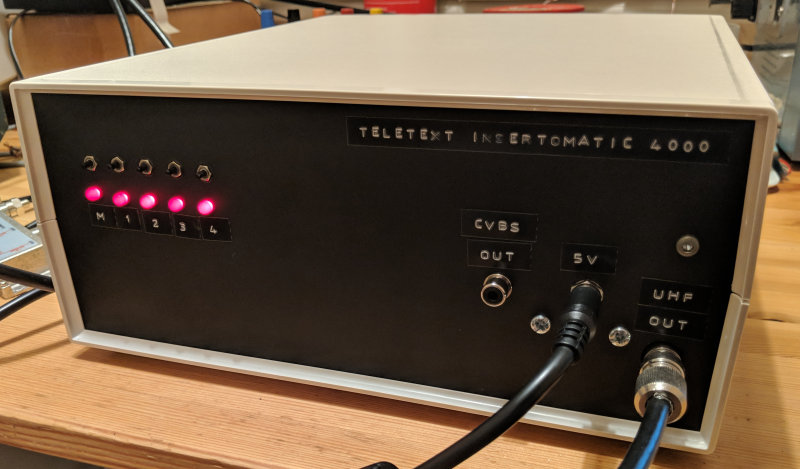
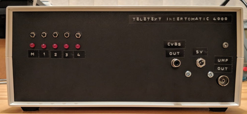
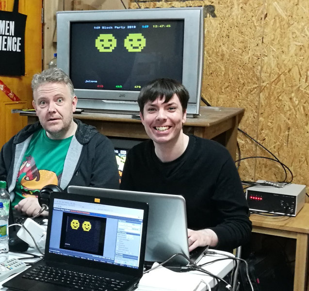 Steve and Dan with the Insertomatic 4000.
Photo courtesy of Tamara Lynn Kwan
The Block Party service is powered by a simple server written in nodejs for Block Party 2017. The web server hosts specially modified versions of the zxnet.co.uk and edit.tf teletext editors, and provides a REST API for them to store and retrieve teletext pages.
The server runs on the Pi zero, and reads and writes the teletext page .tti files in vbit2’s page directory. Version control for each page edit is implemented using git, which this year enabled me to also host the pages almost-live on my online teletext viewer by pushing the pages to an upstream repository on my home server, and running a script at home to frequently pull changes into the teletext viewer’s copy of the pages.
Problems
While the system worked fairly reliably throughout the event, it was not without issues. In the run-up to the event I had severe difficulties with GPU lockups during video playback and teletext output. Omxplayer and teletext would frequently freeze and only resume playback when the teletext binary was killed. This could potentially be a firmware regression and I rolled back to an older version which may have helped but more experimentation is required. [The cause of these freezes has now been identified and a workaround added in raspi-teletext - August 2019]
Additionally rebooting one Pi zero would sometimes cause the other three to crash, which was clearly an issue with power stability. I solved this in a rather crude way by adding 1000µF smoothing capacitors close to each Pi zero and another 2000µF close to the DC input socket where all the supplies tee off from. I had reworked the power wiring two or three times over the weeks and simply ran out of time to entirely redesign the project. A better design might be to have a 12 volt supply for the project with local regulation for each Pi and for the analogue circuitry.
The project box has no ventilation, and gets fairly warm inside with five Raspberry Pi boards and four UHF modulators running. I had initially mounted the “joule thief” tuning voltage module to the case with a double sided adhesive foam pad. This nearly ended in disaster during testing as the heat building up in the case caused the adhesive to soften. I discovered the module hanging at 90° from the case, only supported by a small corner of the foam pad. I’m sure that left much longer it would have dropped onto the components below and shorted out the 5V supply.
The Pi 3B runs with the “sunroof” removed to allow access to the GPIO, and runs the hottest of the 5 boards. The temperature stabilises around 54°C at the Pi 3B CPU, and between 40-45°C for the zeros. If I want to use the project in the summer I will probably have to cut vents at either end of the project box and fit a small fan.