Thank you for purchasing the flash ROM board for your ZX Spectrum +2A/+3, +2B or +3B.
NOTE: This board is NOT compatible with other Spectrum models.
Fitting the flash ROM board
- Disconnect your Spectrum from the power supply.
- Open the case of your Spectrum.
- Carefully remove the two EPROM ICs (Fig 1)
- Carefully insert the flash ROM board into the ROM sockets and clip the A15 and !WE flying leads to the relevant legs of the Z80 and RAM chips (Fig 2)
- Reassemble the Spectrum and reconnect the power.
If you requested unterminated wire ends on your bank select wire solder your toggle switch on before fitting the board.
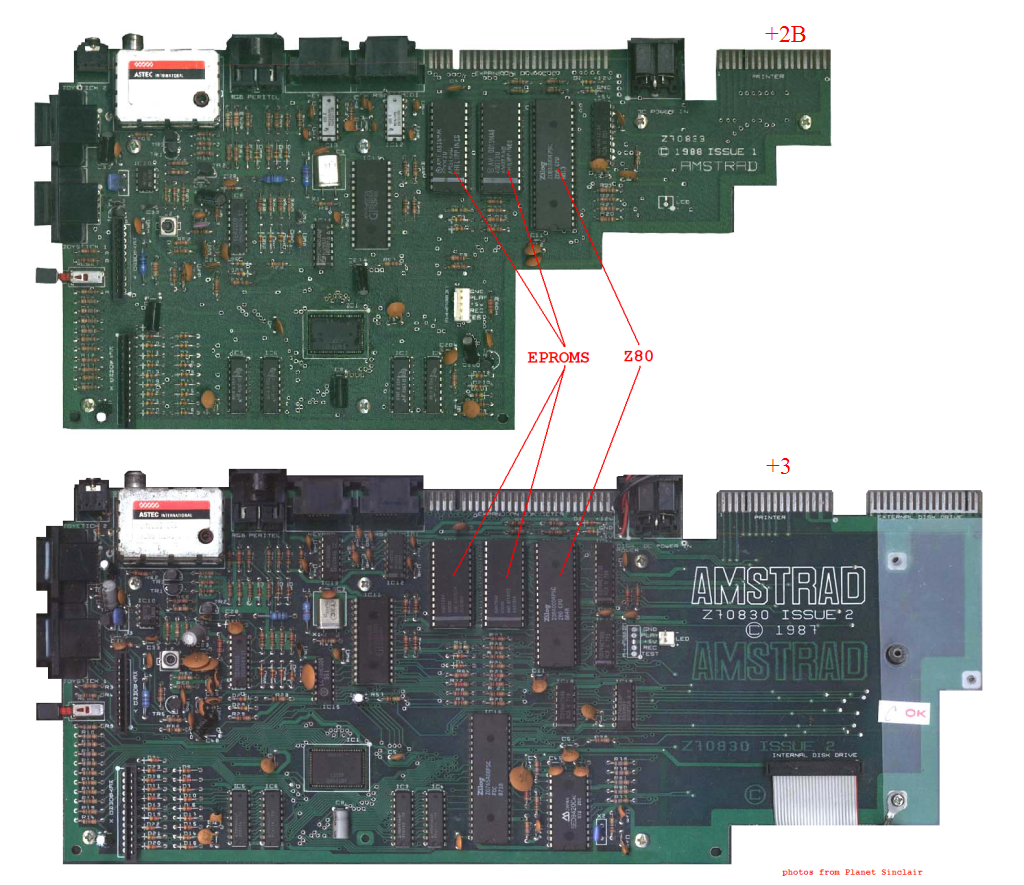
Fig 1.
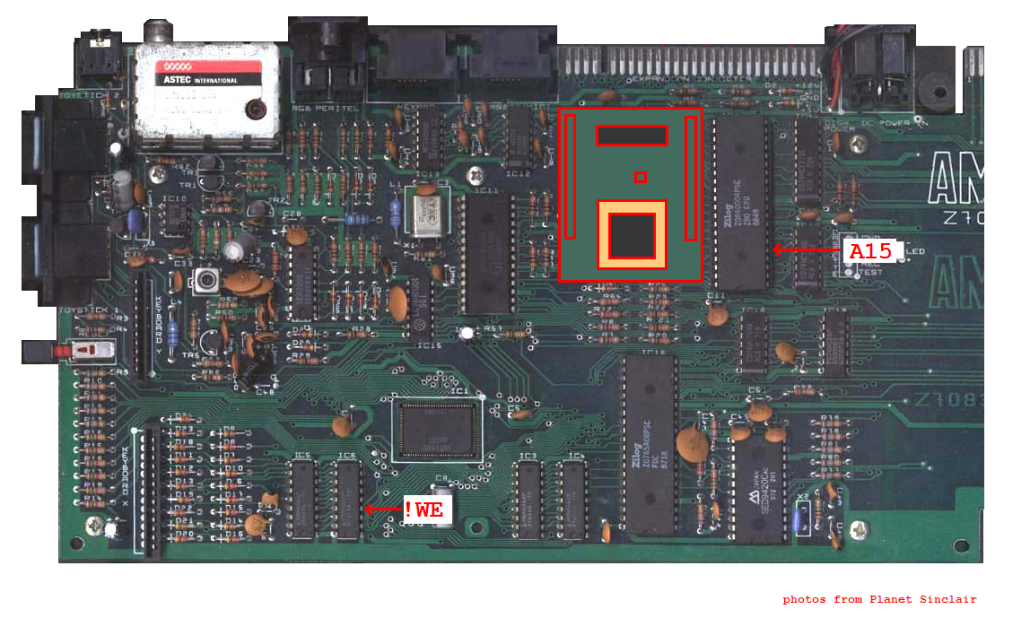
Fig 2.
Selecting a half of the flash ROM
The flash ROM contains 128K. The Spectrum can only see half of this at once. To switch which half of the ROM is in use, move the jumper at the end of the bank select cable (or operate your toggle switch if you fitted one).
NOTE: When the flash programmer has loaded you can switch the half of the flash ROM that the Spectrum sees. The flash programmer software does not require any ROM routines except to load. A ROM version of the programmer is provided pre-programmed on your new board.
Using the write enable jumper
A write enable jumper is used to enable or disable ROM erase and programming operations. When the jumper is connected the ROM can be erased and written. When the jumper is disconnected erase/write operations will fail (RED border in ROM programmer tool)
Using the flash ROM board programmer
Load the "flash.tap" file into the Spectrum from your PC.
The following screen is displayed:
Press the relevant key to select an option.
Options 0 to 3 will copy the contents of the relevant ROM bank to the currently selected RAM bank shown in the bottom left of the screen. (note that these are the ROM Banks visible to the Spectrum, so depend on which half of the flash chip is selected)
Option 4 changes the currently selected RAM bank shown in the bottom left of the screen. There are four RAM banks available, each capable of holding a 16K ROM image. When the software is loaded the RAM banks are empty.
Option 5 changes the currently selected ROM bank, shown in the bottom right of the screen. This is the physical ROM bank that will be flashed with the contents of the current RAM bank.
Option 6 LOADs a 16K ROM image (stored as a CODE file) from cassette to the currently selected RAM bank. (a utility is provided to package a 16k ROM binary into a tap file, this runs on Linux and MS Windows - see Downloads Page)
Option 7 wipes the currently selected ROM bank shown in the bottom right of the screen. If the operation was successful the border goes YELLOW. If it failed, the border goes RED.
Option 8 flashes the contents of the currently selected RAM bank to the currently selected ROM bank (after first performing an erase). If the operation was successful the border goes GREEN. If it failed, the border goes RED.
Option 9 performs a reset and executes the currently paged ROM Bank.